
Il est difficile de faire confiance aux mesures des instruments lorsque l’on ne perçoit pas clairement le mécanisme sous-tendant leur sensibilité et leur précision. Tel est bien souvent le cas des caméras infrarouges. De plus, les discussions sur la précision de mesure des caméras infrarouges s’enferment généralement dans une terminologie et un jargon complexes qui peuvent être source de confusion et d’erreurs. Ceci peut finalement inciter certains chercheurs à rejeter tous ces outils. Cependant, en optant pour cette solution, ils passent à côté des avantages potentiels des mesures thermiques pour les applications de R&D. Dans la discussion suivante, nous analysons les termes techniques et expliquons l’incertitude des mesures en langage simple, pour vous fournir une base qui vous aidera à comprendre l’étalonnage et la précision des caméras infrarouges.
Spécifications de précision des caméras et équation d’incertitude
Vous remarquerez que la plupart des fiches techniques des caméras infrarouges présentent une spécification de précision de ±2 ºC ou 2 % de la mesure. Cette spécification est le résultat d’une technique d’analyse de l’incertitude largement utilisée appelée « Root-Sum-of-Squares » ou RSS. L’idée est de calculer les erreurs partielles pour chaque variable de l’équation de mesure de la température, de mettre au carré chaque terme d’erreur, de les ajouter et d’en extraire la racine carrée. Bien que cette équation paraisse compliquée, elle est en fait assez simple. D’un autre côté, déterminer les erreurs partielles peut être complexe.
Les « erreurs partielles » peuvent provenir de plusieurs variables dans l’équation de mesure de température d’une caméra infrarouge standard, notamment :
- Émissivité
- Température ambiante réfléchie
- Transmittance
- Température de l’atmosphère
- Réponse de la caméra
- Précision de la température de l’étalonneur (corps noir)
Lorsque des valeurs raisonnables sont déterminées pour les « erreurs partielles » pour chacun des termes ci-dessus, l’équation d’erreur générale ressemblera à ça :
![]()
Où les ΔT1, ΔT2, ΔT3, etc. sont des erreurs partielles des variables dans l’équation de mesure.
À quoi ça sert ? Il se trouve que parfois les erreurs aléatoires s’accumulent et vous éloignent de la valeur réelle, alors que d’autres fois elles s’annulent. Prendre le RSS vous donne une valeur qui est plus adaptée pour une spécification d’erreur générale.
Il est nécessaire de préciser que les calculs dont nous avons discuté jusque-là sont uniquement valides si la caméra est utilisée en laboratoire ou à courte distance (moins de 20 m) en extérieur. Les distances plus importantes introduiront une incertitude liée aux mesures en raison de l’absorption atmosphérique et dans une moindre mesure, de ses émissions. Lorsqu’un ingénieur en R&D sur les caméras effectue une analyse RSS pour presque tous les systèmes de caméra infrarouge moderne dans des conditions de laboratoire, le chiffre qu’il obtient se situe autour de ±2 ºC ou 2 %, soit un taux de précision raisonnable pour l’utiliser dans les spécifications de caméras.
Cependant, la pratique a montré que des caméras hautes performances, donnent de bien meilleurs résultats que les caméras économiques, et par conséquent, il nous reste encore du travail pour mieux expliquer cette observation.
Mesures en laboratoire et précision de ±1 ºC ou 1 %
Dans cette section, nous examinons les mesures de température qu’une caméra produit lorsqu’elle analyse un objet dont l’émissivité et la température sont connues. Ce genre d’objet est généralement appelé un « corps noir ». Vous avez peut-être déjà entendu ce terme auparavant en référence au concept théorique d’un objet avec une émissivité et une température connues.
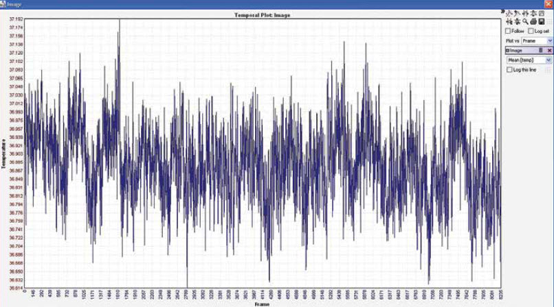
Les mesures d’incertitude du laboratoire comprennent l’orientation d’une caméra étalonnée sur un corps noir étalonné et le traçage de la température sur une certaine durée. Malgré les étalonnages précis, il y aura toujours des erreurs aléatoires dans les mesures. L’ensemble de données obtenu peut être quantifié pour la précision et l’exactitude. L’illustration 2 ci-dessous présente les résultats des mesures de corps noirs étalonnés.
Le tracé ci-dessous présente plus de deux heures de données d’une caméra analysant un corps noir à 37°C à une distance de 0,3 m dans un environnement intérieur. La caméra a enregistré la température une fois par seconde. Les données tracées sont la moyenne de tous les pixels dans l’image. Un histogramme de ces données aurait permis de mieux les comprendre, mais la plupart des points de données se situaient entre 36,8°C et 37°C. Les températures enregistrées les plus éloignées étaient 36,6°C et 37,2°C.
Au vu de ces données, il serait tentant de définir une précision attendue de 0,5°C pour la moyenne de tous les pixels. On pourrait même définir ±1 ºC pour toute autre caméra utilisant le même détecteur. Or, on pourrait également dire que le graphique ci-dessus présente une moyenne de tous les pixels et ne représente pas nécessairement un pixel individuel.
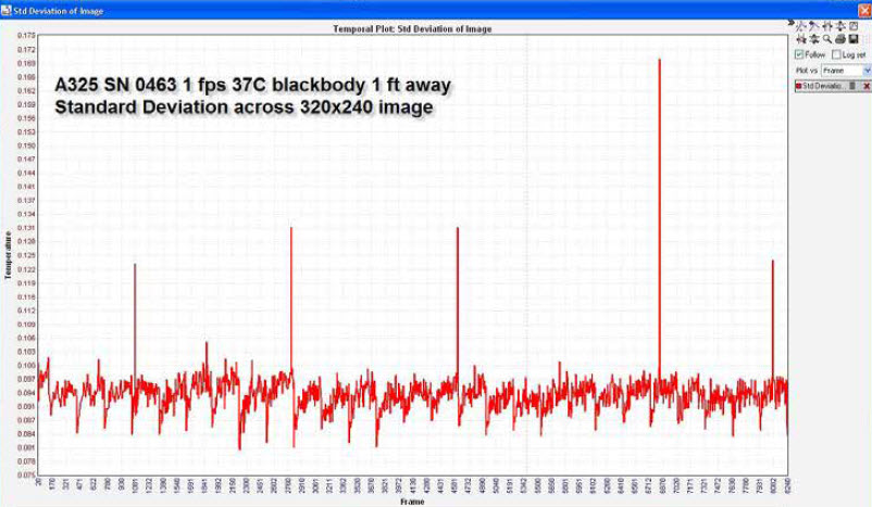
Une façon de savoir à quel point les pixels s’accordent les uns avec les autres est d’examiner l’écart type en fonction du temps. L’illustration 3 en est un exemple. Le graphique montre que l’écart type standard est inférieur à 0,1 °C. Les pointes occasionnelles situées autour de 0,2 °C sont le résultat de la mise à jour ‘1 point’ de la caméra, un type de procédure d’auto-étalonnage que toutes les caméras basées sur des microbolomètres doivent effectuer régulièrement.
Jusqu’ici nous avons discuté du recueil de données à partir de caméras à microbolomètre non refroidies. En quoi les résultats seront-ils différents pour une caméra à détecteur quantique hautes performances ?
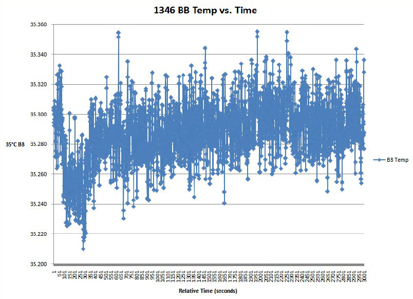
L’illustration 4 présente la réponse d’une caméra 3‐5 μm standard équipée d’un détecteur en antimoniure d’indium (InSb). La documentation de cette caméra présente la précision testée à ±2 ºC ou 2 %. Sur le graphique ci-dessous, on peut voir que les résultats correspondent bien à ces spécifications : la mesure de précision ce jour-là se situait autour de 0,3°C et la mesure d’exactitude autour de 0,1°C. Mais pourquoi l’erreur de décalage était-elle à 0,3°C ? Cela peut être dû à l’étalonnage du corps noir, l’étalonnage de la caméra ou à tout terme d’erreur partielle mentionné dans la section 2. Il est également possible que la caméra ait simplement été en train de chauffer au début de la mesure. Si les optiques ou l’intérieur du corps de la caméra changent de température, ils peuvent fausser la mesure de température.
La conclusion que nous pouvons tirer de ces deux tests d’étalonnage est que les caméras à microbolomètre et les caméras à détecteur quantique à comptage de photons peuvent être étalonnées en usine pour fournir des précisions inférieures à 1°C lorsqu’elles examinent des objets à 37°C dont l’émissivité est connue dans des conditions environnementales intérieures standard.
Compensation de la température ambiante
Une des étapes les plus importantes des étalonnages en usine est la compensation de la température ambiante. Les caméras infrarouges, qu’elles soient thermiques ou à détection quantique, répondent au total de l’énergie infrarouge qui tombe sur le détecteur. Si la caméra est correctement conçue, la majorité de cette énergie sera celle de la scène : très peu d’énergie provient de la caméra elle-même. Cependant, il est impossible d’éliminer complètement la contribution des matériaux entourant le détecteur et le chemin optique. Sans compensation adaptée, toute modification de la température du corps de la caméra ou des objectifs modifiera considérablement les mesures de température fournies par la caméra.
La méthode la plus adaptée pour obtenir une compensation de température ambiante est de mesurer la température de la caméra et le chemin optique dans trois endroits différents (maximum). Les données de mesure sont alors inclues dans l’équation d’étalonnage. Cela permet de garantir des mesures exactes dans toute la plage de températures de fonctionnement (généralement de -15°C à 50°C). Ceci est particulièrement important pour les caméras qui seront utilisées en extérieur ou qui seront soumises à des changements de température.
Même avec la compensation de température ambiante, il est important de laisser les caméras chauffer complètement avant d’effectuer des mesures critiques. De plus, gardez la caméra et les optiques à l’abri du soleil direct ou d’autres sources de chaleur. Modifier la température de la caméra et des optiques aura un effet contraire sur l’incertitude des mesures.
Il est nécessaire de noter que tous les fabricants de caméras n’incluent pas de compensation de température ambiante dans leur processus d’étalonnage. Mais en ne compensant pas correctement la température ambiante, les données de ces caméras pourraient montrer des inexactitudes importantes, allant jusqu’à 10°C ou plus. Par conséquent, n’oubliez pas de poser des questions sur les étalonnages et sur la façon dont ils sont effectués avant d’investir dans une caméra infrarouge.
Autres paramètres de mesures à prendre en compte
Bien que ces paramètres ne soient pas directement liés à l’étalonnage de la caméra, l’émissivité et la taille de point peuvent avoir un impact sur la précision de la caméra. Un paramètre d’émissivité incorrect ou des conditions de test inadaptées affecteront la capacité de la caméra à mesurer correctement votre sujet.
L’émissivité (ou la capacité d’un objet à émettre plutôt qu’à réfléchir l’énergie infrarouge) doit être correctement prise en compte. Cela signifie prendre le temps de déterminer l’émissivité de votre sujet et de saisir ces informations dans la caméra. Cela signifie également savoir si le sujet est entièrement réfléchissant et prendre les mesures nécessaires pour résoudre ce problème (c’est-à-dire recouvrir la surface d’une peinture non réfléchissante) avant d’effectuer les mesures. Toutes les caméras InfraTec fournissent un moyen de définir une émissivité adaptée. Si vous faites une erreur, tous les logiciels InfraTecvous permettent de modifier l’émissivité pendant l’analyse (consultation en direct ou post-analyse). Cette modification peut généralement s’effectuer sur une image complète ou sur une base de région par région.
Un autre facteur à prendre en compte est la taille de point, ou la surface que couvre chaque pixel sur votre cible. Imaginons qu’une caméra A325sc avec un objectif de 25 degrés par défaut mesure une allumette en feu qui se trouve à 18 cm. Chaque pixel couvre environ une surface de 2,5 cm² de la scène totale. Mais une tête d’allumette ne mesure que 0,31 cm², soit une surface bien plus petite que le pixel qui la couvre. Presque toute l’énergie infrarouge qui frappe ce pixel provient en fait de la zone derrière la tête rougeoyante de l’allumette. Seulement 1/64ème de la contribution provient de la tête rougeoyante que nous voulions mesurer. Si l’arrière-plan est à température de la pièce, la caméra sous-estimera considérablement la température de la tête rougeoyante.
La solution serait d’attacher une optique télescopique sur la caméra ou de simplement la déplacer plus près de la cible. Les deux solutions génèreraient une taille de pixel plus proche d’un ratio 1:1 avec la tête rougeoyante. Si nous souhaitons une précision de température absolue la plus exacte possible, nous devons nous assurer que le plus petit objet est entièrement couvert par une grille de 10 x 10 pixels. Cependant, prendre comme taille de point un pixel unique ou une grille 3 x 3 pixels vous rapprochera fortement de la mesure réelle.
Conclusion
Comme nous l’avons vu, la technique d’analyse de l’incertitude RSS nous permet de déterminer la précision des caméras infrarouges et de garantir que celles-ci aient, au maximum, une marge d’erreur de 2°C. Grâce à un étalonnage correct et en tenant compte de facteurs tels que la température ambiante, l’émissivité et la taille de point, la marge d’erreur possible peut être inférieure à 1°C.
Une dernière remarque : les informations présentées dans ce document ont été écrites à l’origine avec des caméras infrarouges étalonnées en usine à l’esprit. Alors que les données physiques sont applicables aux étalonnages effectués par des utilisateurs, les outils et les méthodes nécessaires aux étalonnages effectués par des utilisateurs varient en fonction du système concerné. De plus, savoir effectuer un étalonnage adapté vous permettrait d’effectuer une analyse d’incertitude personnalisée, par conséquent, les spécifications généralisées présentées dans ce document seraient moins pertinentes.

